Buying an electric vehicle charger for global deployment involves more than comparing charging speed and purchase price. A unit may look reliable in a showroom, yet fail beside a dusty highway, a humid port, or a crowded apartment garage. This guide examines why do EV chargers sometimes fail and how buyers can reduce those risks before installation.
Brent Gruber, Senior Director at J.D. Power, has observed, “The public charging experience is not where it needs to be.” His comment reflects a practical industry problem. Charger failures often involve damaged cables, unstable networks, poor thermal management, payment faults, or incorrect installation. One loose connector can interrupt a driver’s journey. One blocked air vent can raise internal temperatures and trigger a shutdown.
Global buyers should review certification, ingress protection, software support, spare-part access, and local electrical compatibility. They should also test chargers under realistic conditions. Dust matters. Salt air matters. So does voltage fluctuation.
No checklist catches every failure.
Field experience remains essential. A supplier may provide impressive laboratory results, but real sites can behave differently. Weather changes. Users misuse equipment. Firmware updates sometimes create new problems, too. That is an uncomfortable point, but it deserves attention.
Reliable procurement requires evidence, not confident promises. Buyers should request maintenance records, warranty terms, remote diagnostic procedures, and independent test results. They should ask who responds at 2 a.m. when a charger stops working. This article offers a practical framework for making that decision with fewer assumptions and better preparation.
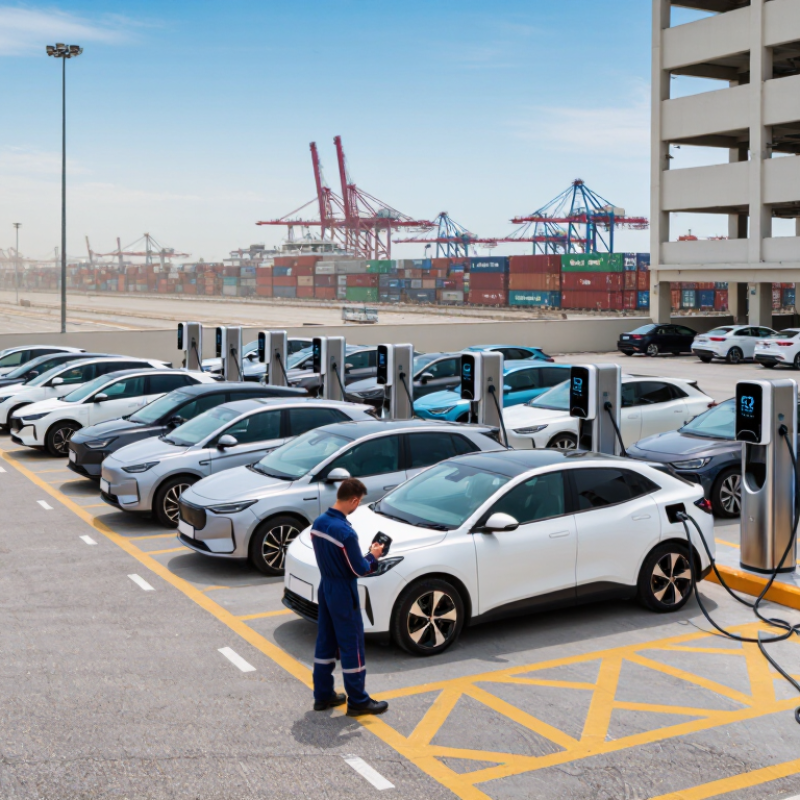
EV charger failures usually begin with small, visible warning signs. A charger may stop mid-session, reduce charging speed, or repeatedly reject a vehicle. These symptoms often point to overheating, unstable voltage, damaged connectors, or communication errors. A hot plug after a short charging session deserves immediate inspection. Heat can result from loose terminals, undersized cables, poor airflow, or worn contact surfaces.
Moisture creates another common failure path, especially in outdoor installations. Water can enter through weak seals, cracked housings, or incorrectly fitted cable glands. Corrosion may develop slowly, making the fault difficult to trace. Internal fans can also fail because of dust buildup, blocked vents, or long exposure to high temperatures. In field checks, technicians sometimes focus on the control board and overlook the ventilation path. That mistake wastes time.
Software and network faults deserve equal attention. A charger may appear functional while its firmware loses communication with the vehicle or payment system. Repeated resets can indicate memory faults, weak power supplies, or incomplete software updates. Global buyers should request test records covering temperature, voltage variation, insulation resistance, connector wear, and emergency shutdown behavior. They should also inspect sample units after transport, not only before shipment. A factory pass does not prove installation readiness. One overlooked detail can become a costly service call.
Global buyers should define technical and safety requirements before comparing supplier prices. The specification should state input voltage, rated current, charging mode, connector type, operating temperature, and enclosure protection. Require compliance with applicable IEC or national standards, plus documented testing for insulation, residual-current protection, grounding, overheating, and water ingress. A low-cost unit can become expensive after installation.
Reliability needs measurable targets. Specify minimum uptime, response times, replacement-part availability, and warranty coverage. The International Energy Agency reported more than four million public charging points worldwide at the end of 2023, with installations rising about 40% that year. Scale increases exposure to weak designs. J.D. Power’s 2024 U.S. study recorded 20.8 problems per 100 public charging visits.
Ask suppliers for factory test records, protection-device certificates, software update procedures, and cybersecurity controls. Require communication compatibility, such as an agreed OCPP version, but verify actual interoperability through live testing. Inspect cable strain relief, terminal torque, ventilation paths, and drainage channels. A thermal camera can reveal abnormal heating during a full-load test. Never rely on photographs alone.
A practical purchase contract should include factory acceptance testing, site acceptance testing, failure reporting, and spare-parts commitments. Define what “operational” means, including payment, authentication, charging, and remote monitoring. No checklist is perfect. Buyers may still overlook local grid quality, installer skill, or harsh weather. That is why pilot deployment across representative sites matters before wider purchasing.
Global buyers can reduce EV charger failures by treating quality verification as a process, not a supplier promise. The International Energy Agency reported more than four million public charging points worldwide at the end of 2023. Public charging networks expanded by over 40% that year. This growth increases pressure on hardware, software, and after-sales support.
Test under load. A qualified laboratory should check insulation, grounding, temperature rise, connector durability, communication stability, and protection against overcurrent. Testing should cover normal charging and abnormal conditions. Ask for complete reports, not only certificates. Results should show test dates, sample numbers, measured values, and applicable IEC standards. Certification confirms a product met defined requirements. It does not guarantee every production unit will remain identical.
Factory audits add practical evidence. Review incoming component controls, calibration records, software release procedures, and final inspection rates. Watch operators test chargers on the production line. Trace one serial number from components to shipment. The IEA’s Global EV Outlook 2024 also highlights rising demand for reliable fast-charging infrastructure, making thermal management especially important. A factory may pass an audit and still have weak field support. That risk is easy to underestimate. Require failure-response timelines, spare-part plans, and periodic batch testing. I would also inspect returned units, because real failures often reveal problems that polished documents miss.
| Quality Dimension | Verification Item | Applicable Reference or Test Basis | Buyer Acceptance Benchmark | Required Evidence |
|---|---|---|---|---|
| 1. Product Design and Electrical Safety | ||||
| Charging control | Control-pilot communication, state transitions, cable detection, and charging interruption | IEC 61851-1 principles for conductive charging systems; destination-market requirements may also apply | Required All defined operating states shall transition correctly, including plug-in, charging, stop, fault, and emergency interruption. |
Type-test report, control-state test records, firmware version, and fault-condition screenshots or logs |
| Electrical protection | Overcurrent, residual-current, overvoltage, undervoltage, overtemperature, and short-circuit protection | Applicable product safety standard and local installation regulations | Required Every specified protection function shall activate at its documented limit and return to a safe state without hazardous heating or exposed live parts. |
Protection-threshold report, schematic, safety-risk assessment, and production test record |
| Insulation and dielectric strength | Insulation resistance, protective bonding, and dielectric withstand | Applicable IEC, EN, UL, or national product standard for the exact charger configuration | Required Pass the voltage, duration, leakage-current, and insulation-resistance limits specified by the applicable standard; no flashover or breakdown. |
Accredited laboratory report and calibrated production-line safety-test records |
| Connector and inlet compatibility | Mechanical fit, contact temperature, locking, insertion cycles, and cable strain relief | IEC 62196 series or the connector standard required in the destination market | Required Connector shall mate correctly, lock securely, maintain contact integrity, and show no cracking, looseness, or abnormal temperature rise after endurance testing. |
Connector specification, endurance test report, contact-temperature data, and incoming inspection records |
| Thermal performance | Temperature rise of terminals, relays, cables, power modules, and enclosure surfaces | Applicable product standard, component ratings, cable rating, and declared operating temperature range | Buyer target Operate continuously at rated output and maximum declared ambient temperature without thermal shutdown, melting, discoloration, or derating outside the published specification. |
Full-load thermal image, temperature log, component derating calculation, and environmental test report |
| 2. Environmental and EMC Reliability | ||||
| Ingress protection | Protection against dust and water entering the enclosure | IEC 60529 IP-code testing; target level depends on indoor, outdoor, pedestal, or wall-mounted installation | Project target Specify the minimum IP rating in the purchase specification. Outdoor units commonly require a documented water-and-dust protection level suitable for the installation environment. |
IP test report for the production enclosure, gasket specification, drainage design, and assembly inspection record |
| Mechanical impact | Resistance to impact on the enclosure, display, socket, and cable holder | IEC 62262 IK-code testing where an impact rating is specified | Project target Use the required IK level for the site risk assessment; no exposed hazardous parts, loss of insulation, or loss of basic function after testing. |
Impact-test report, enclosure material certificate, and post-test inspection photographs |
| Temperature and humidity | Cold, dry heat, cyclic damp heat, and storage-condition testing | IEC 60068 environmental test methods and the charger’s declared operating range | Required Complete the agreed temperature and humidity profile with no safety failure, unacceptable corrosion, condensation damage, communication loss, or permanent performance degradation. |
Environmental chamber profile, before-and-after functional test, insulation test, and visual inspection report |
| Electromagnetic immunity | Electrostatic discharge, electrical fast transients, surge, conducted RF, and radiated RF immunity | IEC 61000-4 series and the EMC standard applicable to the destination market | Required No unsafe charging, unintended energization, permanent damage, or loss of required protection functions at the agreed test levels. Temporary self-recovering interruption must be documented. |
EMC laboratory report, test configuration, firmware version, and immunity-performance classification |
| Emissions | Conducted and radiated electromagnetic emissions | Applicable EMC emissions standard for the charger category and market | Required Measured emissions shall remain below the applicable limits with the final enclosure, cable arrangement, and communication modules installed. |
EMC emissions report using the production-equivalent configuration |
| 3. Software, Communication, and Functional Reliability | ||||
| Firmware quality | Fault handling, watchdog recovery, event logging, update process, and rollback protection | Documented software requirements, cybersecurity procedure, and applicable market regulations | Buyer target No unresolved critical or high-severity defects at shipment; firmware release must be uniquely identified and reproducible. |
Release notes, defect list, test summary, source-controlled build identification, and recovery procedure |
| Communication stability | Ethernet, Wi-Fi, cellular, OCPP, RFID, payment, or local-app functions where included | Contractual protocol version and documented interoperability requirements | Required Successful authentication, session start, metering, stop command, transaction record, and recovery after network interruption. |
Interoperability test report, protocol logs, network-loss test, and data-integrity verification |
| Metering accuracy | Energy measurement, displayed values, stored transaction data, and billing output | Applicable metrology and legal-measurement requirements when used for commercial billing | Required where applicable Accuracy class and verification method shall match the legal or contractual billing requirement in the destination market. |
Meter certificate, calibration record, uncertainty calculation, and end-to-end transaction test |
| Abnormal-condition recovery | Power loss, emergency stop, connector release, communication loss, and repeated restart | Functional safety specification and buyer-approved fault-injection plan | Buyer target Return to a safe state, preserve required transaction data, and resume service only after the defined authorization and safety checks. |
Fault-injection test matrix, event logs, recovery-time record, and restart-cycle results |
| 4. Certification and Compliance Documentation | ||||
| Market certification | Certification and declaration for the exact model, rating, connector, and communication configuration | Destination-market regulatory framework and applicable electrical, EMC, radio, and safety standards | Required Certificate scope, model number, rated input/output, accessories, and factory location shall match the shipped product. |
Current certificate, declaration of conformity, certification schedule, test reports, and authorized-marking artwork |
| Component traceability | Identification of safety-critical components and approved substitutions | Quality-management procedure and certification change-control requirements | Buyer target 100% traceability for safety-critical parts such as relays, residual-current devices, connectors, fuses, cables, power modules, and meters. |
Approved vendor list, bill of materials, component certificates, lot records, and engineering-change notices |
| Calibration control | Calibration status of testers, meters, torque tools, hipot testers, and environmental instruments | Documented calibration system; ISO/IEC 17025 laboratories where external calibration is required | Buyer target 100% of measuring equipment used for product acceptance shall be identifiable, within calibration validity, and protected from unauthorized adjustment. |
Calibration register, certificates, equipment labels, out-of-tolerance procedure, and verification records |
| 5. Factory Audit and Shipment Controls | ||||
| Quality-management system | Document control, nonconformance handling, corrective action, internal audit, and management review | ISO 9001-based processes or an equivalent documented quality system | Buyer target Critical processes documented; corrective actions assigned with owners, due dates, effectiveness checks, and retained evidence. |
Quality manual, process procedures, internal-audit reports, CAPA log, and management-review records |
| Incoming inspection | Inspection of electrical, mechanical, electronic, and safety-critical components | Approved incoming-inspection plan based on risk and component criticality | Buyer target All safety-critical incoming lots shall have defined inspection criteria, sampling rules, acceptance limits, and quarantine controls. |
Incoming inspection records, supplier certificates, sampling plan, quarantine tags, and rejected-lot records |
| Process control | Torque, crimping, soldering, sealing, wiring, programming, and final assembly controls | Approved work instructions and process-control plan | Required Critical process parameters shall be recorded or independently verified; unauthorized rework and component mixing shall be prevented. |
Work instructions, torque logs, crimp-height checks, first-article approval, line-audit records, and rework authorization |
| End-of-line testing | Functional, safety, communication, insulation, grounding, and output tests on finished units | Approved production test specification linked to the released design | Required 100% of finished chargers shall pass documented safety and functional tests before release; failed units shall be uniquely identified and isolated. |
Electronic test records, serial-number linkage, tester settings, failure history, and release approval |
| Final inspection and packaging | Label accuracy, accessories, manuals, cable condition, enclosure appearance, and transit protection | Approved packaging specification and destination-market labeling requirements | Buyer target Correct model, rating label, language, accessories, serial number, and installation documents in every shipment; packaging shall protect against moisture and impact. |
Final-inspection checklist, packaging drop or vibration evidence where required, carton photos, and shipment release record |
| Field-failure feedback | Warranty analysis, return-material authorization, failure classification, and corrective action | Contractual warranty process and continuous-improvement procedure | Buyer target Failure trends reviewed periodically; recurring safety or reliability issues trigger documented root-cause analysis and verified corrective action. |
Warranty dashboard, failure-analysis reports, return samples, corrective-action records, and reliability trend data |
| 6. Recommended Buyer Release Gate | ||||
| Pre-shipment approval | Independent inspection, sample verification, document review, and production-lot release | Purchase specification, approved sample, inspection plan, and destination-market compliance requirements | Release condition Do not ship until critical test failures are closed, certificates match the production configuration, 100% end-of-line testing is complete, and agreed inspection results are accepted. |
Signed inspection report, certificate checklist, test-data export, packing list, serial-number list, and approved corrective-action closure |
Global buyers should treat charger installation as an engineering project, not a plug-in purchase. The International Energy Agency’s Global EV Outlook 2024 reports more than four million public charging points worldwide at the end of 2023. It also projects public charging capacity must expand nearly sixfold by 2035 under its Stated Policies Scenario. That growth makes local grid planning unavoidable.
Before shipment, confirm phase voltage, frequency, fault current, earthing, and transformer capacity. A site rated for 400 volts may still suffer voltage sag during peak demand. Ask the utility for a load study, then specify dynamic load management and surge protection. Leave service clearance around the cabinet. It sounds basic. It is often missed. Test cable length, connector temperature, and software settings during simultaneous charging. A pilot installation can reveal faults that factory testing cannot.
Environmental conditions directly affect failure rates. Install drainage beneath outdoor equipment, seal cable entries, and avoid areas where spray pools. IEC 60529 ingress ratings define dust and water protection, but an IP rating does not prevent corrosion. Coastal sites need compatible metals, coated fasteners, and regular salt inspection. Cold regions need heater controls; hot regions need ventilation and thermal derating. The IEA’s 2024 outlook shows charging demand becoming more distributed, so remote sites deserve equal attention. Planning can still be imperfect. Document every assumption, because grids and weather rarely follow the drawing.
Global EV charger buyers need a maintenance plan before installation begins. Record each unit’s model, location, connector type, and commissioning date. Keep these records in a shared digital system. Technicians should inspect cables, plugs, cooling vents, and emergency stops at scheduled intervals. Dust, moisture, and loose terminals often create avoidable faults. Small issues matter.
Remote monitoring should track charging sessions, voltage changes, temperature, network status, and repeated error codes. Set alerts for abnormal behavior, not every minor event. Too many notifications can hide serious problems. A local technician should confirm critical alarms within an agreed time, even across different time zones. Save diagnostic logs before resetting equipment. Otherwise, useful evidence may disappear.
Warranty procedures should define coverage, exclusions, response times, and replacement responsibilities in clear language. Global buyers should request remote troubleshooting, regional service contacts, and access to approved spare parts. Keep photographs and maintenance records for every claim. This evidence supports fair decisions and reduces delays. However, no procedure works perfectly. Some failures may result from installation conditions, grid instability, or neglected inspections. Review these cases honestly, then update training and maintenance schedules. A practical warranty process should allow technical investigation, not automatic blame.
Recommended operational control targets for maintenance, monitoring, firmware management, and warranty handling across international EV charging deployments.
These baseline targets are practical service thresholds rather than measured failure rates. Local electrical regulations, climate conditions, site usage, and charger manufacturer requirements should be applied when finalizing procedures.
Charging may stop suddenly, slow down, or reject the vehicle repeatedly. A hot plug needs immediate inspection. These signs may indicate overheating, unstable voltage, damaged connectors, or communication errors.
Loose terminals, thin cables, poor airflow, or worn contacts can create heat. Check the plug after a short session. Heat should never be ignored.
Water may enter through cracked housings, weak seals, or poorly fitted cable glands. Corrosion can develop slowly inside the equipment. The outside may look normal.
Dust buildup, blocked vents, and long exposure to high temperatures can stop fans. Technicians sometimes inspect the control board first. That wastes time.
Request records for temperature, voltage variation, insulation resistance, connector wear, and emergency shutdown behavior. Inspect sample units after transport, not only before shipment. A factory pass is not enough.
Confirm phase voltage, frequency, fault current, earthing, and transformer capacity. A site rated for 400 volts may still experience voltage sag. Ask for a local load study.
Multiple vehicles may overload the available supply during peak demand. Use dynamic load management and surge protection where appropriate. Test cable temperature and software settings together.
Provide drainage beneath the equipment and seal every cable entry. Avoid locations where rainwater or spray collects. Coastal sites may need coated fasteners and regular salt checks.
Cold areas may require heater controls. Hot areas need ventilation and thermal derating. Remote sites need attention too. Weather rarely follows the drawing.
Preventing EV charger failures requires a complete quality strategy that begins before supplier selection. Understanding why do EV chargers sometimes fail helps global buyers identify risks such as overheating, unstable power input, communication errors, connector damage, moisture, and poor installation. Buyers should define electrical, safety, performance, and compatibility requirements in advance, then evaluate suppliers through product testing, recognized certification, factory audits, and documented quality-control procedures. These steps can reveal design weaknesses and manufacturing inconsistencies before chargers are deployed.
Reliable operation also depends on proper installation planning. Each site should be assessed for grid capacity, voltage stability, grounding, ventilation, weather exposure, drainage, and physical protection. After deployment, preventive maintenance, remote monitoring, fault alerts, spare-parts planning, and clear warranty procedures can reduce downtime and speed up repairs. By combining technical evaluation, environmental preparation, and long-term service management, global buyers can improve charger safety, extend equipment life, and achieve more consistent charging performance across different regions.

Irvion Charger